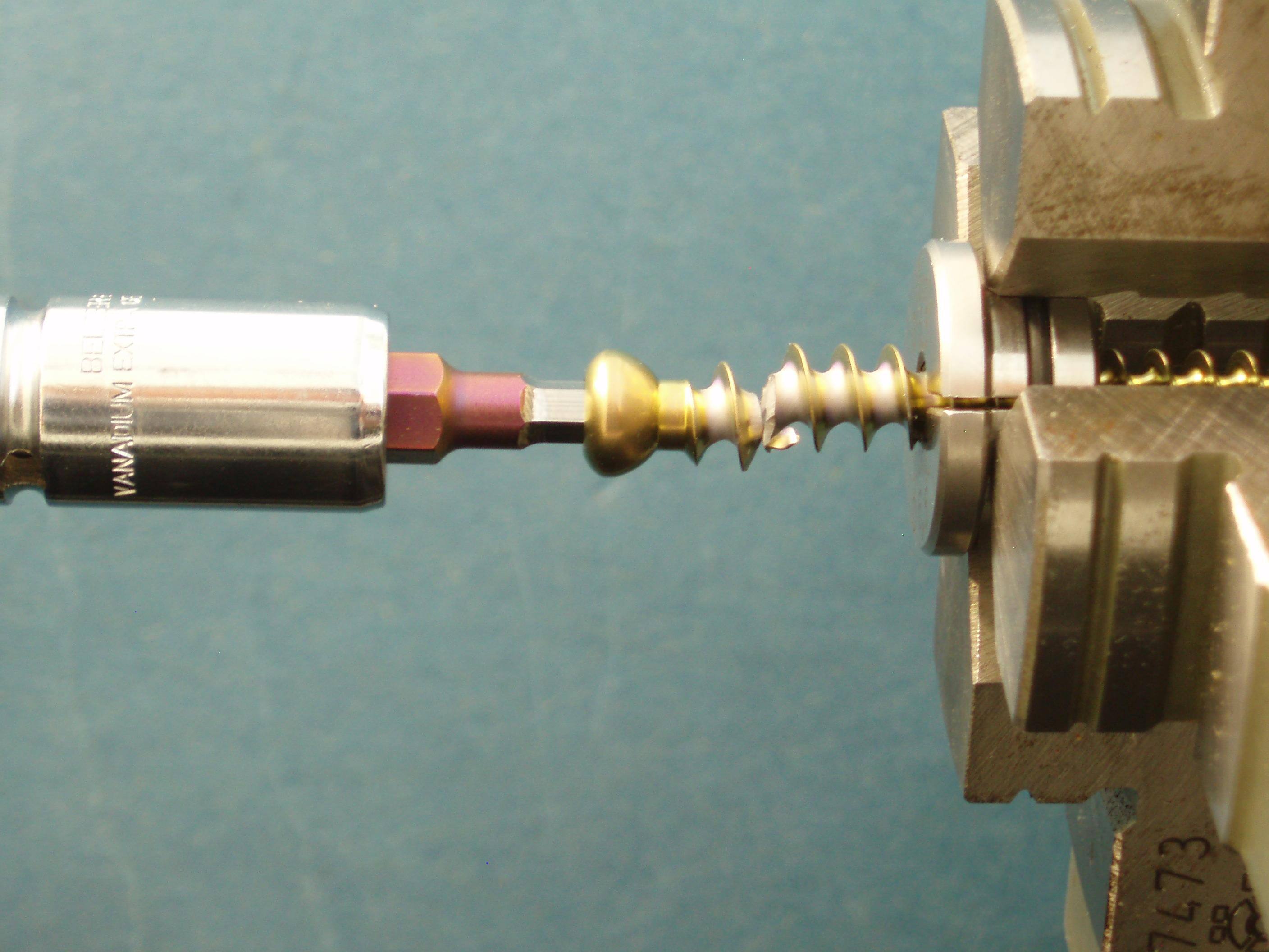
IL-35: Torque- or angle-controlled torsion testing
Do you know the behavior of your products or individual components under torsion? How does the component, the connection or the material behave under torsion? Is there torsional backlash when the load direction is reversed? If you want to clarify such questions, RMS offers with its torsion testing machine an ideal possibility to measure such characteristics.
In order to determine the real behavior of your components under torsional loading, RMS can be helpful with a wide range of applications of its torsion testing machine. Whether conventional turned parts such as screws, shafts and drills or bodies with more complex geometry, a suitable way to securely fix them can always be found. In addition, the parts to be tested can be axially loaded with a constant tensile or compressive load.
During the test, the torque and the torsional angle are continuously recorded. This data can then be used to calculate results such as maximum torque, torque at break, plastic deformation, torsional stiffness, etc., or to detect possible backlash. The tests can be torque- or angle-controlled. In addition, RMS can draw on its wealth of experience in working with a wide variety of materials such as steel, aluminum, titanium, ceramics, plastics or composites.
![]() Figure 1: Zwick‘s TL500 torsion testing machine, with extension for simultaneous static tensile- or compression loading.
Figure 1: Zwick‘s TL500 torsion testing machine, with extension for simultaneous static tensile- or compression loading.
You may also be interested in screwing a screw into a test specimen on the testing machine and then unscrewing it again, or in testing the bending strength or maximum pull-out force on the universal testing machine.
These test methods not only support you in the testing of finished products, but also accompany you throughout the entire product development cycle. In this way, you receive repeated feedback as to which geometry, which material or which production method leads to the torsion properties you require. Thus, you are supported by the RMS in quality assurance and get to know your product and its failure pattern more precisely, which in turn improves risk management. In addition, potential for improvement discovered early in the development process leads to cost savings.
![]()
Figure 2: Functional testing of components to determine the torque at break and the torsional stiffness.
Info about the machine:
- Torsion testing machine from Zwick («TorsionLine TL500»)
- Measuring range: 0 – 500 Nm (via different load cells)
- Control mode: torque- or angle-controlled
- Torque resolution 0.6 ‰
- Angle resolution < 0.003°
- Testing speed 0.036 – 18‘000°/min
- Test space (H x W x L) 220x220x680 mm
- Fixtures for specimens with diameter 0 – 200 mm (manufacturing of individual fixtures for specimens with more complex geometries possible)
